IRCAL is a 1-2.5 µm camera optimised for use with the LLNL
Lick adaptive optics system on the Shane 3 m telescope. Using diamond-turned
gold-coated optics, the camera provides high efficiency diffraction limited
imaging throughout the near-IR. IRCAL incorporates optimisations
for obtaining high dynamic range images afforded by adaptive optics, coronagraphic
masks, and a cross-dispersed silicon grism for high resolution spectroscopy.
The mirrors are kinematically mounted on an Al optical bench that can be removed from the dewar as a single unit. The optical assembly can thus be aligned outside the dewar. Reference holes are machined in the optical bench, to which pinholes that define the optical axis are mounted. Using a laser, the optics can be aligned by adjusting the elements to pass the laser through the pinholes. As the entire assembly is made from homogeneous material, the alignment does not change as the optical bench cools from room temperature to 77K.
Two filter wheels and the pupil mask are housed in a filter wheel assembly box that mounts directly to the cold plate. The filters operate in the collimated beam with a 5 degree tilt to avoid optical ghosts. The wheels are spring loaded onto ruby balls for heat sinking. The mechanisms are geared with stainless steel bevelled gears, driven by stepper motors external to the dewar. The entire optical path is carefully baffled with housings over the optical elements and baffle tubes in between. The interior surfaces of the housings are sandblasted for surface roughness and anodised black. The interior of the baffle tubes are painted black.
The optical elements were manufactured by Janos Technology Inc in diamond
turned aluminum and gold coated. Post polishing was performed by
an IR Labs subcontractor.
| Name | Central
Wavelength |
FWHM | Peak
Transmission |
| ( µ m) | ( µ m) | ( percent) | |
| J | 1.238 | 0.271 | 82 |
| H | 1.656 | 0.296 | 85 |
| K | 2.195 | 0.411 | 75 |
| KS | 2.150 | 0.320 | (1) |
| H2 1-0 S(1) | 2.125 | 0.020 | 80 |
| H I (n=7-4) | 2.167 | 0.020 | 78 |
| J CH4 | 1.183 | 0.040 | 86 (2) |
| K CH4 | 2.356 | 0.130 | 80 |
| 2.2/0.04 | 2.192 | 0.047 | 79 |
| H cont | 1.570 | 0.020 | (3) |
| [Fe II] | 1.644 | 0.016 | (3) |
| K cont | 2.270 | 0.020 | (3) |
Notes:
(1) Specified, not measured.
(2) Unblocked, needs to be crossed with the J filter for blocking.
(3) On order; specified, not measured.
The detector is an AR coated Rockwell 256 x 256 HgCdTe PICNIC array
with 40 µm pixels, sensitive from 0.85 - 2.5 µm.
The SDSU readout electronics also incorporate a 1 µs per pixel readout mode, used with the IR Laboratories IR emission microscopes which interface to the SDSU readout electronics via a SCSI-3 interface. Since the detector has four quadrants, this readout mode exceeds the 2.5 Mpixel/s speed of the optical fiber, and we implement a two quadrant readout at this speed. However, the readnoise is typically 80 electrons RMS in this mode and it has rarely been used.
Since the PICNIC detector uses asynchronous resets on the pixel addressing shift registers, as opposed to the initialising scheme of the NICMOS detectors, it is much easier to implement subarray readouts. It is straightforward for the case that the subarrays are constrained to start at the first pixel in each quadrant. This constraint substantially simplifies the implementation of the clocking for the subarrays by making the clock wave forms for an n x m subarray different from the full 256 x 256 array only in the count of clock pulses (a corollary is that the readout for a 1024 x1024 HAWAII array is the same as a 1024 x 1024 ``subarray''). In practice, subarray readouts are preferable for achieving faster frame rates than faster readout modes, because the readnoise is preserved, and in short exposures the detector is almost always readnoise limited.
The minimum full frame, CDS integration time is 57 ms (3 µs readout) or 24 ms (1 µs readout), though only half the detector well capacity is available because the detector integrates during the first readout of the array. Although we do not provide a separate single read readout mode, it is possible to save the data without the CDS (as a data-cube of raw reads of the detector) if the second read of the CDS is saturated. Because the readnoise is substantially higher (~ 100 electrons RMS) for a single sample, it is generally preferable to use subarrays to speed up the readout when necessary. IRCAL supports subarrays from 2 x 2 up to the full frame. At present, the shortest exposure time for very small subarrays is set by a ~ 5 ms delay after the detector output amplifier is turned on. For a standard CDS readout mode (two full frame resets, two full frame reads), there are four passes through the array to complete the exposure, and it is possible to stream full frame data to disk at ~ 4 Hz (57 ms integration per frame). It is possible to increase this rate (or increase the fraction of integration time) with subarrays, fewer resets, or resetting the detector line by line instead of pixel by pixel (which substantially increases the fixed pattern bias structure because the time between reset and first read differs from pixel to pixel). We have implemented some of these modes for obtaining high frame rate data for observing occultations. In this mode it is possible to make movies for studing transient phenomena such as occultations.
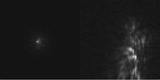 Click
on the movie frame to see an example of a short movie. The right-hand
panel shows the AO-corrected image, the left shows the varying speckle
pattern of uncorrected seeing. The AO corrected images correspond to 10
coadded 57 ms exposures; the speckle movie shows individual 57 ms frames.
Click
on the movie frame to see an example of a short movie. The right-hand
panel shows the AO-corrected image, the left shows the varying speckle
pattern of uncorrected seeing. The AO corrected images correspond to 10
coadded 57 ms exposures; the speckle movie shows individual 57 ms frames.
Facilities are also in place in the user interface for the management of calibrations. The software maintains a list of all exposures taken during an observing session in the form of a palette of readout configurations. This encourages the operator to utilise a homogeneous set of readout configurations throughout the night's observations. The user interface can then generate from this set of readout configurations a script to acquire a complete set of calibration darks.
The user interface incorporates an interface to IDL by loading a dynamic Tcl extension to call the IDL libraries. IDL scripts are used to perform quick-look image manipulation and display. There are facilities for the observers to incorporate their own IDL scripts into the image display (even replacing the image display with a customised IDL tool).
The AO system at Lick observatory is a facility instrument, available to the general user community. Although the calibration and alignment of the AO system in general requires a specialist, the routine observing operations of acquiring objects, dithering exposures (by offsetting the telescope and counter-steering the wavefront sensor to track the guide star) and monitoring the status of the AO loops, do not.
As both the AO system user interface and camera user interface have
been written in Tcl/Tk, we have implemented a method for Tcl remote procedure
calls (rpc) using the Music messaging system. This allows buttons
in one user interface to invoke actions in the other in a straightforward
way. As the two systems have been developed largely independently,
we have found this to be a useful way to present a user with a single screen
to operate both the AO system and IR camera. We have also used this
facility to construct quick, simple distributed scripts. For example,
we use this method of rpc to enable remote operation of a serial port for
communication with motor controllers.
| Band | Camera
efficiency (1) |
System
throughput (2) |
Background | Point source
sensitivity |
| (mag arcsec-2) | SNR = 5 t=300 s | |||
| J (1.25 µm) |
|
0.08 | ... | 21.8 |
| H (1.65 µm) | 0.67 | 0.16 | 14.4 | 20.5 |
| K (2.2 µm) | 0.67 | 0.13 | 9.3 | 17.8 |
| KS (2.1 µm) | ... | 0.14 | 10.3 | 18.3 |
The throughput of IRCAL is excellent, but due to the large number of
surfaces in the AO System, and the telescope itself, the total system throughput
is low, and the emissivity high, hence the high K-band background.
We expect that the throughput will improve this year, as the 3 m primary
has been realuminised and some of the AO system mirrors have been replaced.
K-band image of the Herbig Ae/Be star LkH alpha 234. The image is log
stretched. Total exposure time is 50 s. The 1.5 arcsec companion
is barely visible in the seeing limited image, but the AO system improves
the contrast substantially. Also a companion (1.2 mags fainter) is
clearly detected 0.3 arcsec from the primary with adaptive optics.
Note that each point source is surrounded by a partial Airy ring.
Last updated 18 April 2000
(510) 642-8283
University of California
Astronomy
Berkeley, CA 94720-3411