
Examples of imaging spectrometers are
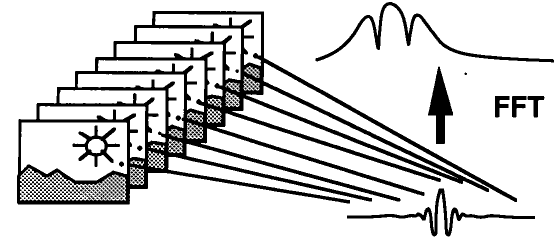
For example, a long slit grating spectrometer which disperses light in 1 spatial dimension and provides imaging data in an orthogonal direction. By scanning of a succession of 1-d slices of the scene a 2-d image may be reconstructioned. Other variants of the DS, are the intral field unit (IFU) and the multi-object spectrometer (MOS), which use different strategies to project the slit on the sky. The IFU slices the slit into short sections, and stacks the slices side by side to provide a contiguous view of thes sky. The MOS either uses fibers or a focal plane mask of slitlets. This could be a filter wheel or Fabry-Perot. An imaging TF acquires a full 2-d image each frame, with successive frames viewed through successive filters. In this case the light is not dispersed, but only a narrow bandpass is transmitted to the detector array. An IFTS acquires a full 2-d image per frame, with successive frames associated with different positions of a moving mirror in an interferometer. The raw data cube for an IFTS consists of the interferogram in 1-d (time) and the 2-d scene in the 2 orthogonal directions of the detector. Fourier transformation of the interferograms for each pixel produces the spectral dimension of the data cube.
Typical rays emerging from two representative points are drawn. One point is located on the optical axis. The second point is displaced by a distance y from the optical axis. The object plane is located at a distance equal to the focal length f of the collimating lens. The object plane may be the focal plane of a telescope. The camera lens, with focal length f' produces an image with magnification (or reduction) factor f/f'.
The depth of field of the focusing system should accommodate twice the
maximum travel distance of the moving mirror in the interferometer in order
to produce a sharp focus in the image plane. The beam splitter transmits
a fraction T of the incident light and reflects a fraction
R.
These coefficients in general depend on polarization, the angle ![]() , and the wavelength,
, and the wavelength, ![]() . For monochromatic light of wavenumber
. For monochromatic light of wavenumber ![]() , the intensity of light at the image point y' relative to the intensity
emerging from the object point y is proportional to
, the intensity of light at the image point y' relative to the intensity
emerging from the object point y is proportional to ![]() . The phase difference
. The phase difference ![]() is determined by the round trip optical path difference x for the
moving mirror with respect to its zero phase difference (ZPD) point, and
the angle
is determined by the round trip optical path difference x for the
moving mirror with respect to its zero phase difference (ZPD) point, and
the angle ![]() , between the collimated rays and the optical axis,
, between the collimated rays and the optical axis,
![]()
For a non-monochromatic point source, the observed light intensity I(x,y') in the focal plane is a function of both mirror position x and the distance from the optical axis y'. For a spectral distribution with intensity for wave numbers between k and k+dk given by S(k)dk, and a detection efficiency E, the observed light intensity in the focal plane is given by
![]()
The light intensity at any given radius y' is thus simply related to the Fourier transform of the spectrum. Introducing the modified frequency
![]()
and the modified spectrum ![]() , the observed intensity is
, the observed intensity is
Here is a simulation of the fringe pattern predicted by Eq (4).
By Fourier transforming I(x,y') as a function of x, the spectrum S'(k') can be recovered, and thus S(k) itself.
Ordinarily, a range of values of y' are integrated, which has the effect of broadening and shifting a monochromatic line in the spectrum which is recovered from the Fourier transform of I(x). This is the origin of the Jacquinot limit on the resolution of an FTS. For a Jacquinot stop of radius r, to first order in r/f, the total width of the Jacquinot blurring is
![]()
For points off the optical axis, this blurring varies linearly with
distance from the optical axis. In terms of the angular position ![]() and spread
and spread ![]() of a given pixel, this limit to the spectral resolution is given by
of a given pixel, this limit to the spectral resolution is given by
![]()
Except for extremely high resolution instruments, this limitation is small compared to the limit on the resolution from the total travel distance of the moving mirror.
Reference: Bennett,
C. L., Carter, M. R., Fields, D. J. & Hernandez, J. 1993,
Proc.
SPIE, 1937, 191